pigpio library
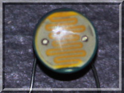
pigpio pigpio C I/F pigpiod pigpiod C I/F Python pigs piscope Misc Examples Download FAQ Site Map

Rotary Encoder Example

The following code shows one way to read an incremental mechanical rotary enoder (the sort used for volume control in audio systems).  These rotary encoders have two switches A and B which return a quadrature output, i.e. they are 90 degrees out of phase.

SETUP
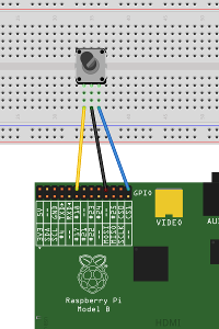
fritzing diagramThe common (centre) terminal should be connected to a Pi ground.

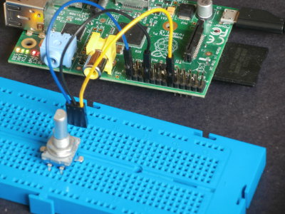
The A and B terminals may be connected to any spare gpios.

Here A to gpio18 (P1-12), common to ground (P1-20), B to gpio7 (P1-26).

photo of set-up

CODE

#include <stdio.h>

#include <pigpio.h>

/*
   Rotary encoder connections:

   Encoder A      - gpio 18   (pin P1-12)
   Encoder B      - gpio 7    (pin P1-26)
   Encoder Common - Pi ground (pin P1-20)
*/

#define ENCODER_A 18
#define ENCODER_B  7

static volatile int encoderPos;

/* forward declaration */

void encoderPulse(int gpio, int lev, uint32_t tick);

int main(int argc, char * argv[])
{
   int pos=0;

   if (gpioInitialise()<0) return 1;

   gpioSetMode(ENCODER_A, PI_INPUT);
   gpioSetMode(ENCODER_B, PI_INPUT);

   /* pull up is needed as encoder common is grounded */

   gpioSetPullUpDown(ENCODER_A, PI_PUD_UP);
   gpioSetPullUpDown(ENCODER_B, PI_PUD_UP);

   encoderPos = pos;

   /* monitor encoder level changes */

   gpioSetAlertFunc(ENCODER_A, encoderPulse);
   gpioSetAlertFunc(ENCODER_B, encoderPulse);

   while (1)
   {
      if (pos != encoderPos)
      {
         pos = encoderPos;
         printf("pos=%d\ ", pos);
      }
      gpioDelay(20000); /* check pos 50 times per second */
   }

   gpioTerminate();
}

void encoderPulse(int gpio, int level, uint32_t tick)
{
   /*

             +---------+         +---------+      0
             |         |         |         |
   A         |         |         |         |
             |         |         |         |
   +---------+         +---------+         +----- 1

       +---------+         +---------+            0
       |         |         |         |
   B   |         |         |         |
       |         |         |         |
   ----+         +---------+         +---------+  1

   */

   static int levA=0, levB=0, lastGpio = -1;

   if (gpio == ENCODER_A) levA = level; else levB = level;

   if (gpio != lastGpio) /* debounce */
   {
      lastGpio = gpio;

      if ((gpio == ENCODER_A) && (level == 0))
      {
         if (!levB) ++encoderPos;
      }
      else if ((gpio == ENCODER_B) && (level == 1))
      {
         if (levA) --encoderPos;
      }
   }
}

BUILD

cc -o rotary_encoder rotary_encoder.c -lpigpio -lrt -lpthread

RUN

sudo ./rotary_encoder

While the program is running you can capture the waveform using the notification feature built in to pigpio.  Issue the following commands on the Pi.

pigs no
pig2vcd  </dev/pigpio0 >re.vcd &
pigs nb 0 0x40080 # set bits for gpios 7 (0x80) and 18 (0x40000)

Twiddle the rotary encoder forwards and backwards for a few seconds.  Then enter

pigs nc 0

The file re.vcd will contain the captured waveform, which can be viewed using GTKWave.


Overview

rotary encoder waveform overview

Detail of switch bounce.  Contact A bounces for circa 700 us before completing the level transition
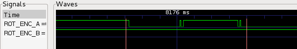
rotary encoder waveform detail
[pigpio] [pigpio C I/F] [pigpiod] [pigpiod C I/F] [Python] [pigs] [piscope] [Misc] [Examples] [Download] [FAQ] [Site Map]
© 2012-2020
e-mail: pigpio @ abyz.me.uk
Updated: 30/04/2020