| pigpio
pigpio C I/F
pigpiod
pigpiod C I/F
Python
pigs
piscope
Misc
Examples
Download
FAQ
Site Map
|
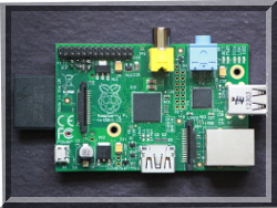
The pigpio library
pigpio is a library for the Raspberry which allows control of the
General Purpose Input Outputs (GPIO). pigpio works on all
versions of the Pi.
At the moment pigpio on the Pi4B is experimental. I am not
sure if the DMA channels being used are safe. The Pi4B defaults are
primary channel 7, secondary channel 6. If these channels do not
work you will have to experiment. You can set the channels used by
the pigpio daemon by invoking it with the -d and -e options, e.g.
sudo pigpiod -d 5 -e 8 to specify primary 5,
secondary 8.
Download
Features
-
hardware timed sampling and time-stamping of GPIO 0-31 every 5
us
-
hardware timed PWM on all of GPIO 0-31
-
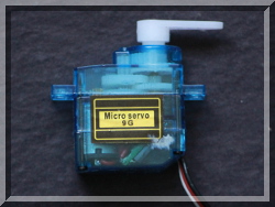
hardware timed servo pulses on all of GPIO 0-31
-
callbacks on GPIO 0-31 level change (time accurate to a few
us)
-
notifications via pipe on GPIO 0-31 level change
-
callbacks at timed intervals
-
reading/writing all of the GPIO in a bank (0-31, 32-53) as a
single operation
-
GPIO reading, writing, modes, and internal pulls
-
socket and pipe interfaces for the bulk of the functionality
-
waveforms to generate GPIO level changes (time accurate to a few
us)
-
software serial links using any user GPIO
-
rudimentary permission control through the socket and pipe
interfaces
- creating and running scripts on the pigpio daemon
General
The pigpio library is written in the C
programming language.
The pigpio daemon offers a socket and pipe interface to
the underlying C library.
A C library and a Python module allow control of the GPIO via the
pigpio daemon.
There is third party support for a number of other languages.
piscope
piscope is a logic analyser (digital
waveform viewer).
piscope is a GTK+3 application and uses pigpio to provide raw GPIO
level data. piscope may be run on a Pi or on any machine
capable of compiling a GTK+3 application.
GPIO
ALL GPIO are identified
by their Broadcom
number. See
elinux.org
There are 54 GPIO in total, arranged in two banks.
Bank 1 contains GPIO 0-31. Bank 2 contains GPIO
32-53.
For all types of Pi it is safe to read all the GPIO. If you try to
write a system GPIO or change its mode you can crash the Pi or
corrupt the data on the SD card.
There are several types of board, each with different expansion
headers, giving physical access to different GPIO.
Type 1 - Model B (original
model)
- Hardware revision numbers of 2 and 3.
- User GPIO 0-1, 4, 7-11, 14-15, 17-18, 21-25.
|
GPIO |
pin |
pin |
GPIO |
|
| 3V3 |
- |
1 |
2 |
- |
5V |
| SDA |
0
|
3 |
4 |
- |
5V |
| SCL |
1
|
5 |
6 |
- |
Ground |
|
4 |
7 |
8 |
14 |
TXD |
| Ground |
- |
9 |
10 |
15 |
RXD |
| ce1 |
17 |
11 |
12 |
18 |
ce0 |
|
21 |
13 |
14 |
- |
Ground |
|
22 |
15 |
16 |
23 |
|
| 3V3 |
-
|
17 |
18 |
24 |
|
| MOSI |
10 |
19 |
20 |
- |
Ground |
| MISO |
9 |
21 |
22 |
25 |
|
| SCLK |
11 |
23 |
24 |
8 |
CE0 |
| Ground |
- |
25 |
26 |
7 |
CE1 |
Type 2 - Model A, B (revision
2)
26 pin header (P1) and an additional 8 pin header (P5).
- Hardware revision numbers of 4, 5, 6 (B), 7, 8, 9 (A), and 13,
14, 15 (B).
- User GPIO 2-4, 7-11, 14-15, 17-18, 22-25, 27-31.
|
GPIO |
pin |
pin |
GPIO |
|
| 3V3 |
- |
1 |
2 |
- |
5V |
| SDA |
2 |
3 |
4 |
- |
5V |
| SCL |
3 |
5 |
6 |
- |
Ground |
|
4 |
7 |
8 |
14 |
TXD |
| Ground |
- |
9 |
10 |
15 |
RXD |
| ce1 |
17 |
11 |
12 |
18 |
ce0 |
|
27 |
13 |
14 |
- |
Ground |
|
22 |
15 |
16 |
23 |
|
| 3V3 |
-
|
17 |
18 |
24 |
|
| MOSI |
10 |
19 |
20 |
- |
Ground |
| MISO |
9 |
21 |
22 |
25 |
|
| SCLK |
11 |
23 |
24 |
8 |
CE0 |
| Ground |
- |
25 |
26 |
7 |
CE1 |
|
GPIO |
pin |
pin |
GPIO |
|
5V
|
- |
1 |
2 |
- |
3V3 |
SDA
|
28 |
3 |
4 |
29 |
SCL |
|
30 |
5 |
6 |
31 |
|
Ground
|
-
|
7 |
8 |
-
|
Ground |
Type 3 - Model A+, B+, Pi
Zero, Pi Zero W, Pi2B, Pi3B, Pi4B
- 40 pin expansion header (J8).
- Hardware revision numbers of 16 or greater.
- User GPIO 2-27 (0 and 1 are reserved).
|
GPIO |
pin |
pin |
GPIO |
|
| 3V3 |
- |
1 |
2 |
- |
5V |
| SDA |
2 |
3 |
4 |
- |
5V |
| SCL |
3 |
5 |
6 |
- |
Ground |
|
4 |
7 |
8 |
14 |
TXD |
| Ground |
- |
9 |
10 |
15 |
RXD |
| ce1 |
17 |
11 |
12 |
18 |
ce0 |
|
27 |
13 |
14 |
- |
Ground |
|
22 |
15 |
16 |
23 |
|
| 3V3 |
-
|
17 |
18 |
24 |
|
| MOSI |
10 |
19 |
20 |
- |
Ground |
| MISO |
9 |
21 |
22 |
25 |
|
| SCLK |
11 |
23 |
24 |
8 |
CE0 |
| Ground |
- |
25 |
26 |
7 |
CE1 |
| ID_SD |
0 |
27 |
28 |
1 |
ID_SC |
|
5 |
29 |
30 |
- |
Ground |
|
6 |
31 |
32 |
12 |
|
|
13 |
33 |
34 |
- |
Ground |
| miso |
19 |
35 |
36 |
16 |
ce2 |
|
26 |
37 |
38 |
20 |
mosi |
| Ground |
- |
39 |
40 |
21 |
sclk |
Compute Module
All 54 GPIO may be physically accessed. Some are reserved
for system use - refer to the Compute Module documentation.
Only GPIO 0-31 are supported for hardware timed sampling, PWM,
servo pulses, alert callbacks, waves, and software serial
links.
Other
Languages
There are several third party projects which provide wrappers
for pigpio.
Some I am aware of are:
- Erlang
(skvamme)
- Java JNI
wrapper around the pigpio C library (mattlewis)
- Java via
diozero, a high level wrapper around pigpio, Pi4J, wiringPi etc
(mattlewis)
- Java
(nkolban)
- .NET/mono
(unosquare)
- Node.js
(fivdi)
- Perl (Gligan
Calin Horea)
- Ruby
(Nak)
- Smalltalk(Instantiations)
- Xojo(UBogun)
The PWM and servo pulses are timed using the DMA
and PWM/PCM peripherals. This use was inspired by Richard
Hirst's servoblaster kernel module.
|